A section is used to show the detail of a component or an assembly on a particular plane which is known as the cutting plane. What is Full Section.

Sectioning Technique Engineering Design Mcgill University
A full cross section displays the whole view whereas a local cross section shows a portion of the model within a closed boundary cross-sectioned but not outside the closed boundary.

. Full sections half sections broken sections rotated. This kind of construction drawing helps identify the primary structures in relation to other surrounding structures of the building. Rib And Web Section 13.
A revolving view is effective for elongated objects or. Revolved section aligned section 6. Figure 20 - Front view and half section.
The Cutting-Plane Line The cutting-plane line represents the edge view of the cutting plane see Figure 8-3. The diagonal lines on the section drawing are used to indicate the area that has been theoretically cut. In both cases the object should be standing on its base when the.
Full section 2. FIGURE PART OR LOCAL SECTIONS Part at a to detail of type u normal the maln m drawings in this THE FULL SECTIONAL VIEW the d FIGURE 310. Types of Section in Engineering Drawing.
Put into a drawing to show an area not normally shown. The three main types of pictorial drawings that are extensively used in architectural presentations are perspective drawings isometric drawings and oblique drawings. The view is made by passing the straight cutting plane completely through the part.
Full section in a full section the cutting plane line passes fully through the part. An elevation drawing is a view taken from a point outside the object without any slicing. The lines are thin and are usually drawn at a 45-degree angle to the major outline of the object.
Removed section detailed section 21. Section lines are thin lines. A cutting plane does not necessarily need to cut the whole object.
A skill requirement 1. There are three major types of sections used in engineering drawing. Aligned Section Revolved Sections Used to show a small portion of a drawing.
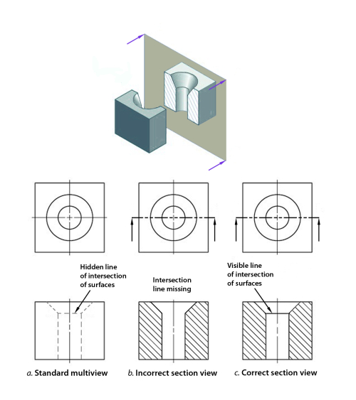
Half sections are commonly used to show both the internal and outside view of symmetrical objects. A cutting plane line shows where object was cut to obtain the section view. Ribs and spokes can be left un-lined for better clarity in the section view.
The main difference between isometric and typical perspective drawings is that in the latter the lines recede to vanishing points. Section Section Callout or Blow Up Section Plan Detail Site Plan Reflected Ceiling Plan or RCP Plan Section Elevation Drawings. Further section drawings also provide information for the types of materials to be used in the construction.
Section line symbols are chosen according to the material of the object Section lines are generally drawn at a 45 angle. The different types of sectional views assist them in this process. Lines Used in Section Views ¾Section Lines.
At each end of the line draw a short line with an arrow to show the direction for looking at the section. A section drawing is a view taken after you slice an object then look at the surface created by the slicing. Understanding in a conventional practice for each kind of sections.
DISPLACEMENT OF HOLES IN SECTION ciralar in out-ting at pitch from in raffer 32 Drawing sectional views In orthogonal to complete of an ng Intemally of a The of C line to Nhlch it The of a lire type A. These lines are called section lining or cross-hatching. 88 Plan B Revolved sections.
Partial or Broken Out Section 4. Kind of sections 1. You can create a cross section in Part and Assembly modes and show it in a drawing or you can add it to a view in drawing mode while you are creating it.
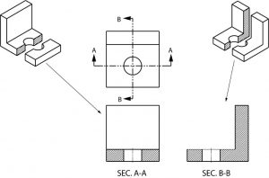
The first form is more commonly used. 81 and it is required to draw three sectional viewsAssume that you had a bracket and cut it with a hacksaw along the line marked B-B. The view is made by passing the bended cutting plane completely through the part.
Removed section detailed section 7. Normally a view is replaced with the full section view. Full Section If the imaginary cutting plane passes through the entire object splitting the drawn object in two with the interior of the object revealed this is called a full section A full section is the most widely-used sectional view.
As the name suggests the section drawings show the structure in a sliced form. A few of the more common ones are. Broken crosshatching shows where cutting plane line intersections material each material has its own crosshatching cutting plane line shows where the imaginery knife cuts thru the part line is always parallel to a line of rotation shows which cutting plane line goes to the section.
ASME specifies two forms for cutting-plane lines as shown in Figure 8-4. Here is an object sectioned from two different directions. This means they are not drawn in perspective and there is no foreshortening.
Dimensioning to dotted lines is not a recommended practice. All parts and details are rotated into the section view. Figure 19 - Full and sectioned isometric views.
A simple bracket is shown in Fig. Section lines are used to indicate where the cutting plane cuts the material. This type of drawing avoids the necessity of introducing dotted lines for the holes and the recess.
There are a number of different types of sectional views that can be drawn. Revolved section aligned section 6. - इजनयरग डरइग म सकशन क परकर 1.
Show a cross-section of an area turned 90 degrees or perpendicular to the object. Ability in orthographic visualization 2. There are three major types of sections used in engineering drawing.
Full section The view obtained even the cutting plane is right across the object. What is Half Section. Types of section views 1.
Section drawings are orthographic projections with the exception of section perspectives. There are different types of section drawings. The second shows up well on complicated drawings.
Sectional views in engineering technical drawings Half Sectional views. You will learn about them from now on 22. Last Updated on Sat 23 Oct 2021 Engineering Drawing Symmetrical parts may be drawn half in section and half in outside view.
K half section The view Obtained When the cutting plane goes half way across the Object to the centre line.
Sectioning Technique Engineering Design Mcgill University

Design Handbook Engineering Drawing And Sketching Related Resources Design And Manufacturing I Mechanical Engineering Mit Opencourseware
2
2
Engineering Drawings

Sectional Views

Engineering Drawings
Sectional Views Basic Blueprint Reading
0 komentar
Posting Komentar